WP3: Structural Load Alleviation
The large prop-rotors on Tilt Rotor aircraft are required to work effectively in helicopter mode as an edgewise rotor and as a propeller in airplane mode. They are also required to generate and sustain the manoeuvre loads in these flight regimes and also during conversion mode when the nacelles can be fixed at intermediate angles, e.g. 60°. These requirements introduce significant structural and aerodynamic design challenges but also opportunities.

Figure 1: XV15 research aircraft during conversion
The objectives of these studies about the opportunity for active control of structural loads are to:
-
improve understanding of the load-critical aspects specific to tilt rotor aircraft,
-
assess risks of exceeding structural design loads during manoeuvres,
-
simulate structural loads during manoeuvres,
-
explore and define control features to prevent structural load exceedances,
-
support integration and assessment of control features in piloted simulation.
The partners involved are Eurocopter Deutschland, CIRA and the University of Liverpool, who leads the work package. The work is being conducted in three main activities - defining the critical loads, modelling the critical loads and designing active control solutions to load alleviation that do not degrade handling qualities.
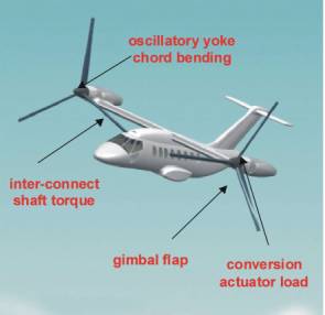
Figure 2:Typical critical loads of a tilt rotor
Modelling and Validation of Tilt-rotors
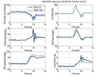
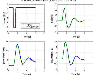
As part of the activities of the structural load alleviation (SLA) work package, Liverpool have developed a mathematical model of the Bell XV-15 aircraft based on published data. The model was developed in the FLIGHTLAB environment with off-line and real-time piloted simulation capabilities and designated as FXV-15. Comparisons of flight test data and the results from the aircraft manufacturer's simulation model were performed against FXV-15 results. Comparisons of the basic trim and dynamic response of the aircraft were good and gave a high level of confidence that the basic flight characteristics of a tilt-rotor aircraft can be adequately simulated in the FLIGHTLAB environment, before the transfer of the modelling activities to the Eurocopter EUROTILT configuration. As the next step EUROTILT configuration, into which ultimately the SLA components will be implemented, is modelled in FLIGTLAB (F-EUROTILT) and validated against the Eurocopter HOST model. The validation showed very good comparisons between the two models and this allowed the design of the SLA controllers using the linear models produced from the F-EUROTILT model.
![]()
![]()
Simulation of the Critical Structural Loads
The initial aim of the RHILP project was to develop control concepts to alleviate all of the critical loads listed shown in Figure 2. As the project progressed, due to a number of unforeseen reasons it was clear that this objective would not be wholly met and hence a decision was made among the RHILP partners to concentrated on just one of the 6 critical loads mentioned above. So, the work concentrated on the oscillatory yoke chord bending loads in airplane mode, with some limited attention also given to gimbal flap bearing loads.
![]()
![]()
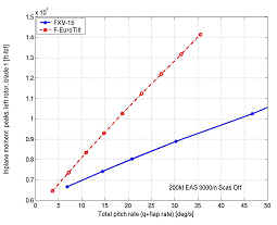
Figure 5 shows plots of the peak in-plane moments against the sum of aircraft pitch rate and the longitudinal gimbal flap rate from the FLIGHTLAB EUROTILT and XV-15 models with stability and control augmentation disengaged. For the development of SLA controllers it is necessary to develop linear output equations relating the controlled variable (in-plane bending) with available measurements. Linear output equations representing the envelope of the n/rev blade in-plane moments is derived by transforming the individual blade loads into a multi-blade-coordinate system. Output equations for the in-plane load envelope was also approximated by a linear function of gimbal tilt rate and aircraft pitch rate. Both methods were found to be useful in representing the moment envelope during pitch manoeuvres in the control design process
Synthesis and Analysis of In-plane Load Controllers
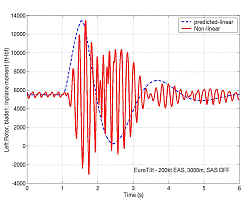
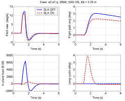
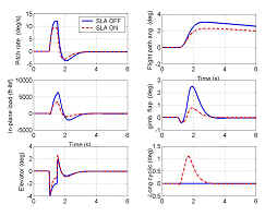
Two approaches to SLA system design have been developed, viz., m-synthesis and H-infinity. The m-synthesis approach used longitudinal cyclic as the controller output whereas the H-infinity method used elevator and cyclic for load reduction. In addition, the H-infinity method was formulated as a dual-objective problem, to suppress both the in-plane load and the gimbal longitudinal flap. Considerations of the trade-offs between performance and the HQs for the design and off-design conditions, in the presence of multiplicative output uncertainty, led to the selection of a SLA system that used gimbal angles and pitch rate as feedback measurements. For the case of the m-synthesis design, a 7-state controller with 4 degs control authority provided acceptable performance with moderate degradation of handling qualities for the 200 kts flight condition, as well as in the two specified off-design cases (160 kts EAS at sea-level and 225 kts EAS at 3,000 m). For the same reference manoeuvre, the 4-state H-infinity controller used approximately 1.2 deg of cyclic in addition to the elevator feed back. The performance was inferior (due to the reduced cyclic authority) compared to m-controller whereas the flapping remained within 1 deg compared to the 3 deg excursion for the m-controller.
Flight path quickness and a complementary load metric, namely load quickness were suggested as the measures in the evaluation of load suppression and handling quality effects. To the same end, frequency responses of flight path angle and pitch rate with SLA-on vs. SLA-off were also investigated.
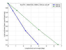
![]()
![]()
Figures 9 and 10 show, respectively, the peak values of the in-plane moment, normalised with respect to its maximum value in the open loop situation, and the normalised flight path quickness parameter, as functions of maximum displacement of longitudinal cyclic due to controller activity. The results show that, as expected, performance improves for higher control authority with an associated penalty on the flight path quickness. For example for the SAS-off case, and with a cyclic authority of 4 deg, the 57% reduction in yoke load quickness is accompanied by a reduction in flight path quickness of about 8%. Full load suppression requires about 7deg cyclic with SAS-off giving a corresponding HQ degradation of about 20%.