|
K2 is
a
motor-driven star tracker that I designed and built to
allow
photographs of the
night sky to be taken without the photographs showing
star trails due
to the rotation of the Earth. I wanted to be able to
take the star
tracker on holiday to Kenya (on the equator) and
photograph the skies
there that are unaffected by light pollution.
|
||
So the star tracker
had
to be:
|
In practice,
this means:
|
|
ConstructionAs this was my second star tracker (I built my first one when I was a student at college) I called it K2. I decided to construct K2 from lengths of L-section and U-section aluminium bolted together as this is very strong and very light. The sections make two 'T' shapes, the static base T and the moving top T. The pivot is provided by two brass hinges that connect the two T's together, positioned at the ends of the top bars of the T's. When operating the two T's are pushed apart by a bolt driven at 1 rpm by a small motor and gearbox. The design is optimised for low latitudes (within 20° of the equator), but will also work in the UK (latitude 52°) provided that the camera and lens are not so heavy that they put the whole system out of balance. |
||
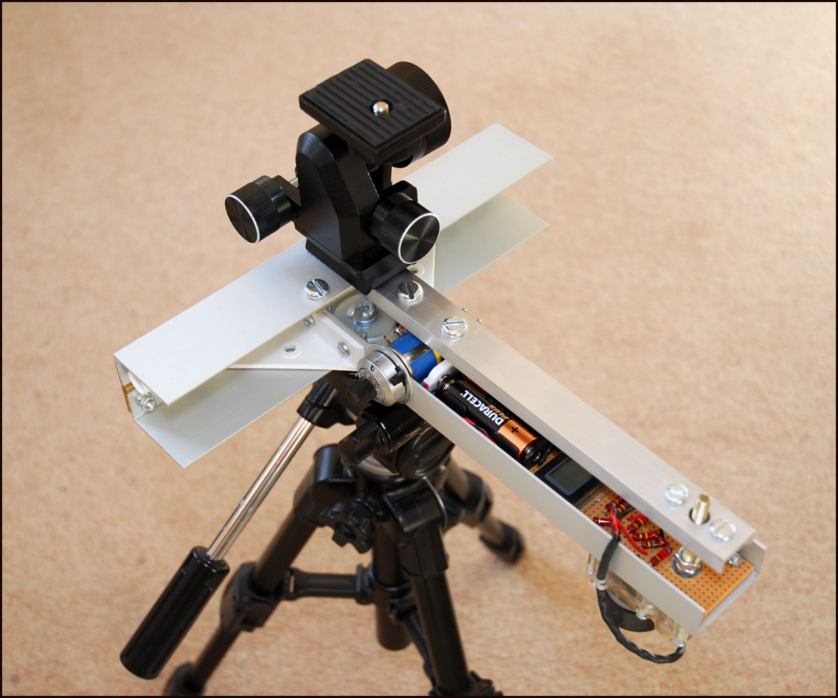 K2 in operating configuration |
 K2 opened to show components |
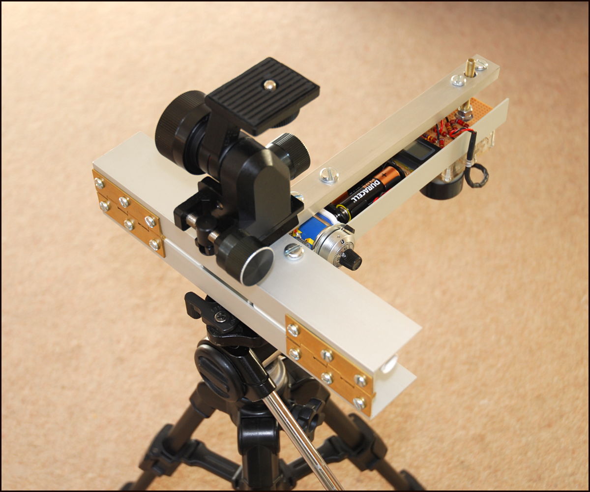 Hinges give a smooth movement |
|
The M6
bolt
has a 1 mm pitch and is positioned 230 mm from the
hinge axis. A nut
sits on the bolt and is driven upwards as the bolt
rotates (the nut cannot rotate as it is
constrained within the U-section arm that forms the
length of the top
T). Driving the bolt at 1 rpm forces the top T
to rotate at approximately 1/230 of a radian per
minute, or one
revolution per day, to counteract the rotation of the
Earth. The design
is much more accurate than a conventional tangent
drive and much
simpler than a double-arm drive. The reason for the
high accuracy is
explained, with technobabble, here.
|
||
|
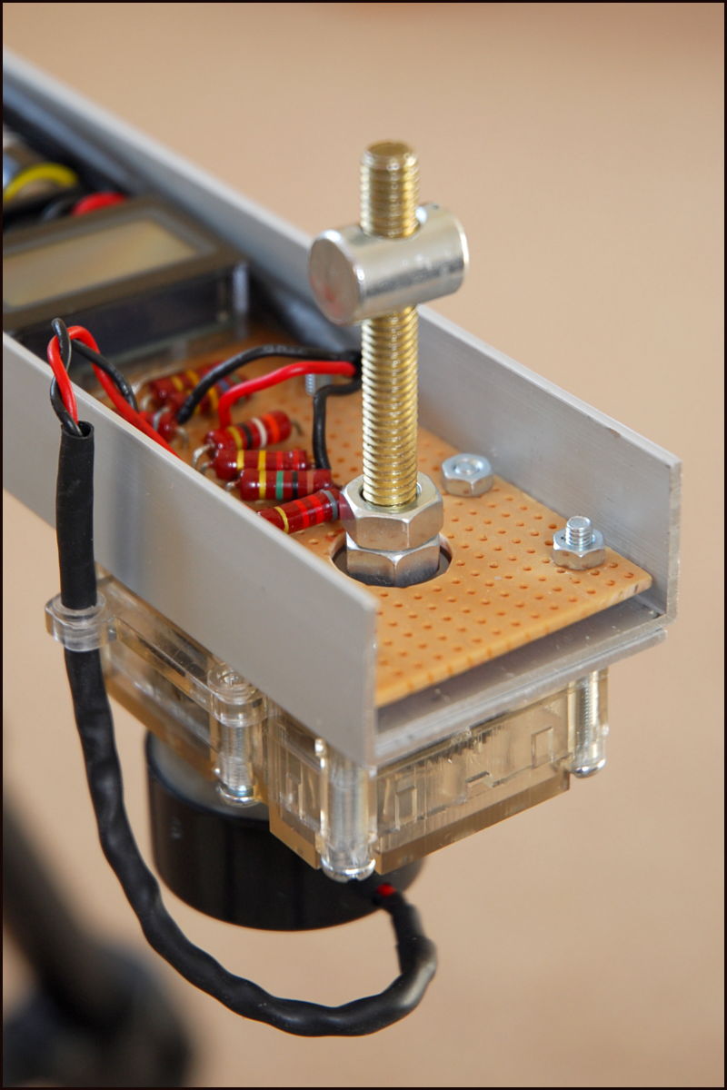
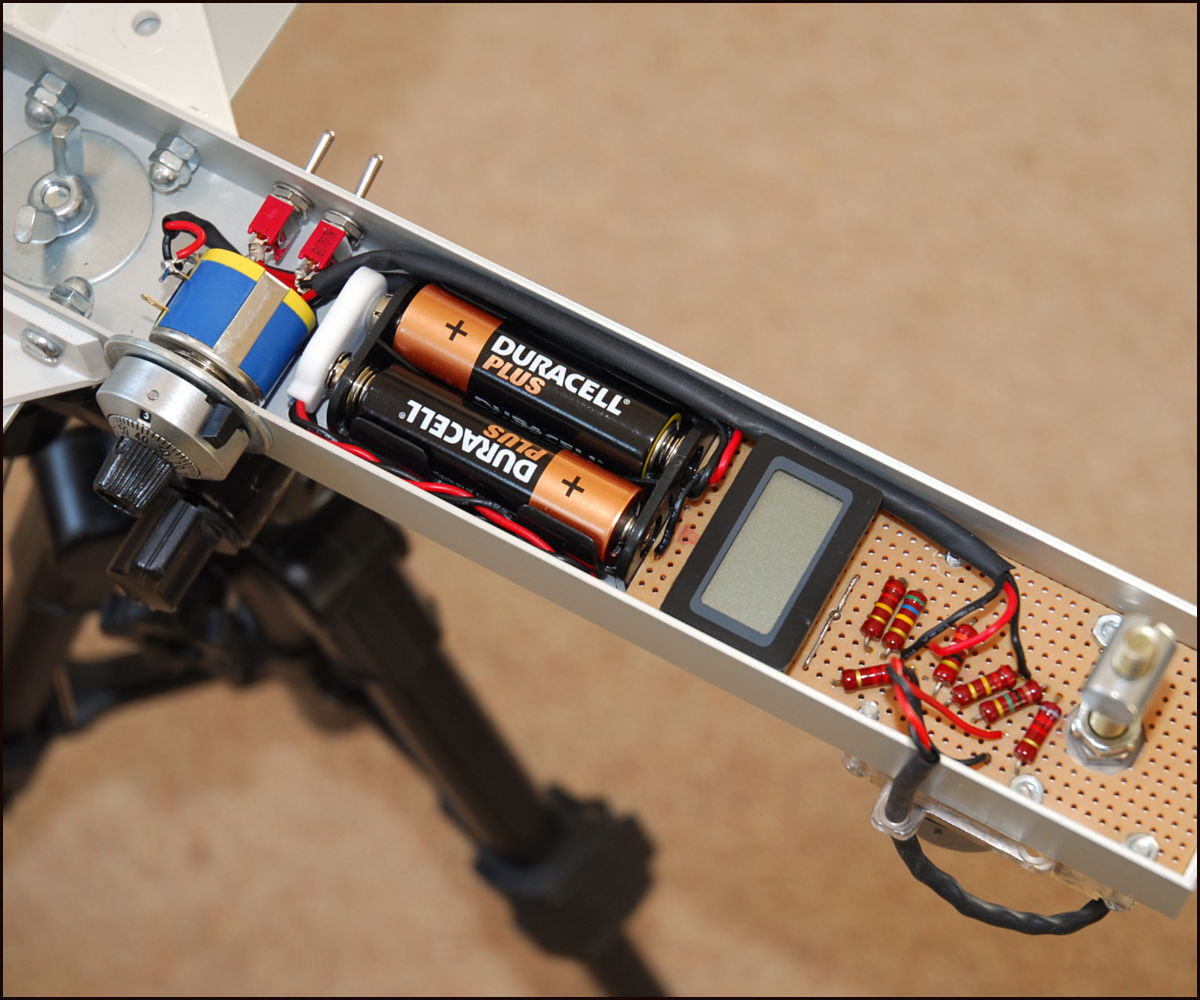 Close-up of components |
|
| In
practise,
the tracking accuracy of K2 is determined by the degree
of alignment
between the hinge axis and the Earth's axis. A polar
scope, used in
some commercial star trackers, is useless if Polaris is
on the horizon.
An alternative method of alignment is to use an
inclinometer and a
compass to set the altitude and azimuth, respectively. A
digital
inclinometer is accurate to 0.1°, but even a
digital compass is only accurate to about 1°
and you have to know the offset between magnetic North
and true North
for your location. Inaccurate polar alignment is the
biggest factor
that affects the overall
tracking accuracy of K2 and I am thinking about ways to
improve it. |
||
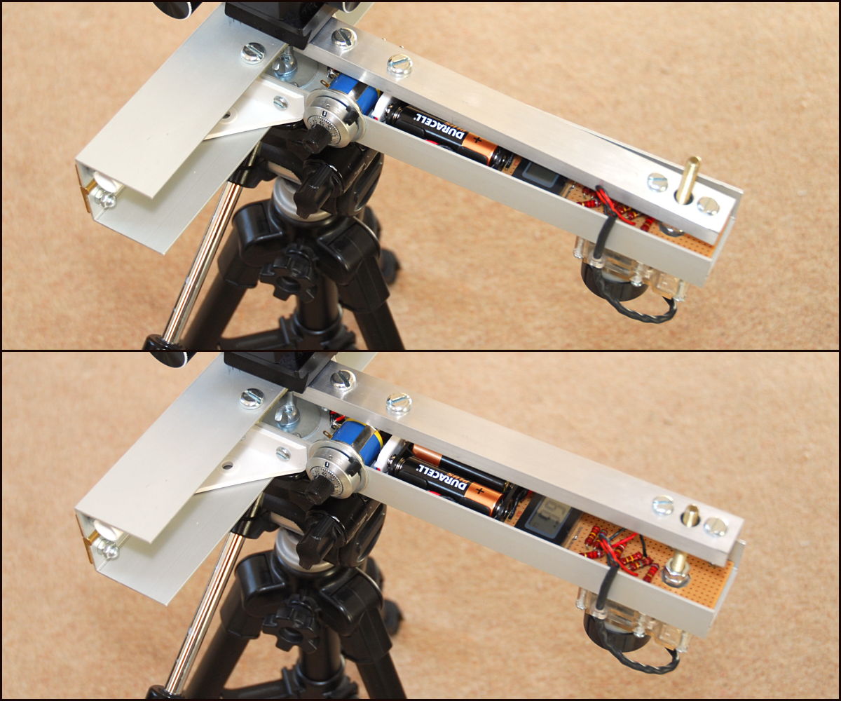 Movement after 15 minutes driving |
The
image on the left shows K2 at the start (top) and end
(bottom) of a
15-minute run. The motor has turned the bolt 15
revolutions, pushing the nut 15 mm upwards along the
bolt and rotating
the top T by about 4° from its starting
position. At this point the top T can be lifted
off the nut and the nut spun back down the bolt by
hand, ready to start
another 15-minute run.
Note that the direction of the bolt moves slightly as the top T moves relative to the base T. The nut moving on the bolt is cylindrical (see close-up image below right) and so the contact point on the underside of the top T 'rolls' over the cylinder. Small strips of teflon on the underside of the top T ensure that the contact between the nut and top T is smooth. |
|
| The
layout
of the components inside the base T is shown in the close-up image above
right. The
resistors are
arranged in two sets. One set is a
potential divider to drop the 3 V supplied by the two AA
batteries down
to the 2.3 V that is needed to drive the motor at 1 rpm
(3 V drives it
at 1.3 rpm). The second set is used to drop either (i)
the voltage
supplied by the batteries or (ii) the voltage across the
motor down to
the appropriate value for display on the LCD voltmeter.
As the
voltmeter is set to read a maximum of 1.999 V (for
maximum resolution)
the battery voltage is divided by 2 and so displays 1.5
V when the
batteries are fresh. The voltage across the motor is
divided by 2.3 so
that the voltmeter reads 1 V when the motor has 2.3 V
across it (and is
rotating at 1 rpm). Thus, the voltmeter effectively
reads rpm. |
 Cylindrical
nut
on drive bolt
|
|
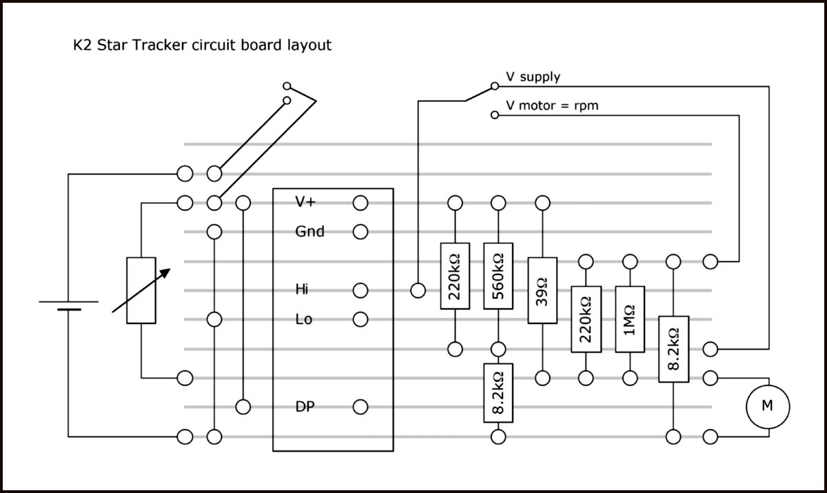
Layout of
circuit components
|
The
layout of
the components inside the base T is shown in the circuit
diagram on the left.
The potentiometer is in parallel with one of the
resistors in the
potential divider that drops the battery supply
voltage down from 3 V
to 2.3 V. This allows the voltage across the motor,
and hence the speed
of the drive, to be adjusted to compensate for the
slow drop in voltage
of the batteries as they gradually run down. When
starting a
photography session, the potentiometer is adjusted
until the voltmeter,
set to read the voltage across the motor (divided by
2.3), reads 1.000
rpm. Over a 15-minute period, the battery voltage will
hardly change at
all, but it can be checked at the end of each
15-minute session when
the top T is lifted to spin the nut back to its
starting position. The
voltage supplied by a battery changes with
temperature, so it's worth
keeping an eye
on it over the course of a night as the temperature
drops.
As K2 was built with hand tools, I could not guarantee that the dimensions were exactly as per theoretical design. This is not a problem. For instance, if when constructed it turns out that the distance from the drive bolt to the hinge axis is 231 mm, rather than 230 mm, then the motor can be set to drive at 231/230 = 1.004 rpm. |
|