
Boats have many places where liquids are kept and it is important to monitor the level. Low tech solutions: dipstick, sight gauge, looking inside,.. are traditional.
For fuel storage, it is convenient to have an accurate readout - to monitor usage and to plan refuelling. Here I focus on options.
My experience of fuel tanks on motor boats: my first boat had a resistive sender (float that slid up and down two wires so varying resistance with a display as a moving needle gauge). This gave very imprecise readings and then malfunctioned completely. My second boat had a tank with an access cap that could be unscrewed and a dipstick inserted. This was failsafe and reliable when in flat calm but rather time consuming to operate.
So I decided to update the system - ideally with a cheap and reliable system that conveniently displayed an accurate reading.
An added complication is that some fuel tanks may not be cuboid - so the level is not directly proportional to the volume remaining. Also because of fuel sloshing around, some means of determining an average level is needed. Another factor is that, if a boat heels, the reading should be taken in the centre of the tank to minimize bias.
I looked into capacitative senders: they require quite sophisticated
electronics to analyse the signal, so are expensive (about £200). Some
can output a signal as NMEA2000 which means that a MFD can display it (so no
need for a separate display, but with cost of extra NMEA cabling and
connectors). Some have the option to calibrate a tank of irregular shape also.
This is the system now used on top-end power boats. The senders are claimed to be
accurate to a few mm. Another advantage is that they can be cut to length as
needed.
One issue is that water has a very different dielectric constant
from fuel (or air) - which means the reading becomes modified if some water is
stirred into the fuel - this is claimed to be a useful "feature" that enables
fuel contamination to be detected.
A cheaper option is a resistive sender. Car senders are "swinging arm"
mostly and are not very reliable or accurate. The marine environment (salty
air) degrades the surface of the variable resistor element.
A more reliable
resistive sender uses a sealed vertical column with a series of reed switches
inside, connected to resistors. The reed switch is activated (closed) by a
magnetic field and a float with magnets inside it can activate the switches
without any marine air getting at them. These are available with a typical
separation of switches of 20mm in level. An option of smaller (10mm)
separation also is available. For my tank with a 450mm vertical
extension, 20mm separation gives 4.5% increments - so a volume reading with
maximum relative error of 2.2%. That is about the precision that I got with a dipstick.
Resistive senders are mostly designed for cars and there are two different conventions in use (values in ohms): European 10(empty) 190(full); US 240(empty) 30(full). Also the fitting to the hole in the top of the tank can be (i) traditional SAE 5-hole fitting or (ii) 1.25 inch BSP.
I have a 1.25 inch BSP fitting on my tank for the tank inspection cap. So a reed-switch resistive sender with that top fitting would fit directly in place of the cap. This is less commonly available than the standard 5-hole fitting, but can be ordered. Manufacturers include WEMA (Europe-based) and KUS (Chinese). I ordered a Chinese 400mm long (length options every 50 mm and recommended 50mm gap below bottom of sender to bottom of tank) sender with US-style resistance range (eBay cost £23 in 2017).
On the bench, I then measured the resistance (with a multimeter) while moving the float to different positions. There is some hysteresis: the reading changes at a different position when moving up than when moving down. Overall there were 18 different readings in the 350 mm range of travel of the float with average separation 20.5 mm. These resistance readings are not quite linear - possibly to emulate traditional swinging-arm senders and/or to expand the scale near empty.
My plot of level (mm)[with 70mm ullage addded] versus resistance (ohms).
Armed with this calibration information, I could then relate each of the 18
possible resistance readings to a level and hence a volume of fuel stored.
(1) In my spirit of economy, I connected a cheap multimeter across the leads to
read resistance. This could then be converted to a volume reading using a table
I printed out. Cost of a multimeter is a few pounds, but I had a spare, that had
some functions no longer working, but which showed resistance accurately.
This was much more convenient than raising the floorboards, unscrewing the tank-cap,
inserting the dipstick, holding the dripping dipstick to read the level, cleaning up
drips of fuel and putting cap and floor back in place. It did, however, still
have to be done in calm conditions to get a steady reading.
How to do better?
Given my computing and electronics expertise, I took up the challenge to
achieve this myself. A promising way forward was to use an Arduino computer
board. These are designed to take voltage input and to give a voltage output after
processing. Introducing "damping" would also be easy to achieve. An Arduino
Uno R3 board is about £10 depending on manufacturer.
Arduino
A clone of an Arduino board (Uno R3) is readily available. You will need
a USB cable (with printer-type termination: USB-B) and a computer (Windows, Mac or Linux)
to program the board. The board has analogue voltage input pins (returning integer
0,..1023 as voltage is 0,..5 volts). Since the board has a 5V output pin (low current only),
one can determine resistance using a divider: connect R0 between +5V and analogue pin and
connect sender resistance R between the same analogue pin and ground (GRD).
Display:
My program is here .
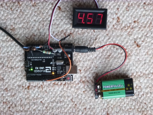
A further issue is providing power to the Arduino and to the voltmeter. When
programming it, with USB connection to a computer, power is provided by the USB.
For the eventual stand-alone use, power needs to come from somewhere else. Options are
a 9V battery with suitable plug (there is an input jack on the Arduino that optimally
should be provided with 7 to 9V); a USB plug from a USB charger if you have one onboard;
or a DC to DC drop-down board to reduce the boat electricity supply (12v or 24v nominal)
down to about 8v which can be applied to the power input socket.
So what is needed: Arduino Uno R3, USB cable, a resistor (R0), an LED voltmeter and some
wire to connect. Plus a source of power (7-9v if a USB input is not available) and
maybe an on/off power switch too.
An Arduino board is designed for prototyping and wires have push-in connections. I am
experimenting with a more "rugged" way of connecting. I am happy to solder, heat-shrink,
etc.
I also explored other display options from the Arduino:
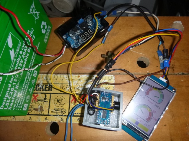
"Ruggedised" set up on test bench: thermistor probe (£2,
mounted in brass screw fitting at centre), 12/24 to 7v
dropper (switch-mode, £4.31), Arduino nano (cost just over
£2) with pins and board soldered on (also with active 5V buzzer),
nextion display (£16).
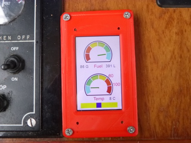
Finally: installed on boat. Here is display (bezel 3D-printed thanks to
Julian). It was a cold day: 8°C.
Display
Automobile (moving needle) displays are cheap but are fairly inaccurate.
Automotive bar-graph displays also exist but typically have a resolution of 12% or worse.
(2) I drew up a plan to use a simple circuit to convert the resistance value into a
voltage proportional to the fuel volume: this is illustrated as a curve on the figure above.
Voltage can be displayed by a small LCD/LED block (cost few £) which could be mounted
on the engine diagnostic panel.
This seemed to be a rather sub-optimal approach: the curve does not track the data
exactly - so extra error would be introduced. A better solution would be to have
the option to translate the resistance values accurately to volume values.
Cruzpro make such a device, but it is rather expensive (FU60: £200).
Then voltage at pin will be R/(R+R0) times 5 volts. This can be
solved to give the unknown R in terms of R0 and the voltage ratio at pin / 5
volts. It is sensible to choose a value of R0 similar to the values covered by
R: I used 257 ohms since I had such a resistor handy (resistance measured by
same multimeter used to calibrate the sender). A larger value of R0 will mean
less current flows (current is 5/(R+R0) Amp so 19mA maximum in my case) which
can help battery life (see below).
In my case, since there are only 18 possible resistance values, I select the
one nearest to the measured value of R. This then gives the corresponding depth of the
float above its bottom position from my bench measurements. From the tank geometry the depth
can be converted into volume of fuel (in litres and/or gallons).
If you have a tank with complicated geometry - just add fuel 10
litres at a time (say), measuring the level with a dipstick to calibrate the
relationship between depth and volume.
How to display the result? (it is actually shown on the computer screen
used to program and set up the board - useful for checking, but not for boat
use). The most accurate method would be to get an LCD/LED display that can be
driven by the Arduino. These are readily available (for instance some "starter
packs" include them) but are quite fiddly to connect and of unknown
reliability on board a boat.
(3) A much cheaper option, with very much simpler wiring, is to use the
option to output a variable voltage (0,..5V) from one of the Arduino PWM pins.
This can then be read by a cheap digital voltmeter (for instance a 3 digit LED
voltage display 0-30V with separate power input line of more than 3V costs a
few pounds only). Such a display only has three leads so is easy to fit to a
boat console and it appears quite robust. So one arranges to send out a
voltage (between 0 and 5V) that carries the volume message required: for
example 3.01V for 301 litres or 0.66V for 66 gallons.
There is one catch: PWM means Pulse Width Modulation and the output
pin has output varying regularly from 0V to 5V with the average voltage
representing the "output voltage". This is specified as an integer 0,...255
representing the fraction of maximum. If the voltmeter has a suitable
averaging circuit built in, it will read this average correctly. If not, one
can either calibrate it and correct for any shift or use an RC filter to
average the signal before sending it to the voltmeter. I found that, in my
case, the shift needed for correction was small, so applied it in the program.
Image of prototype setup.
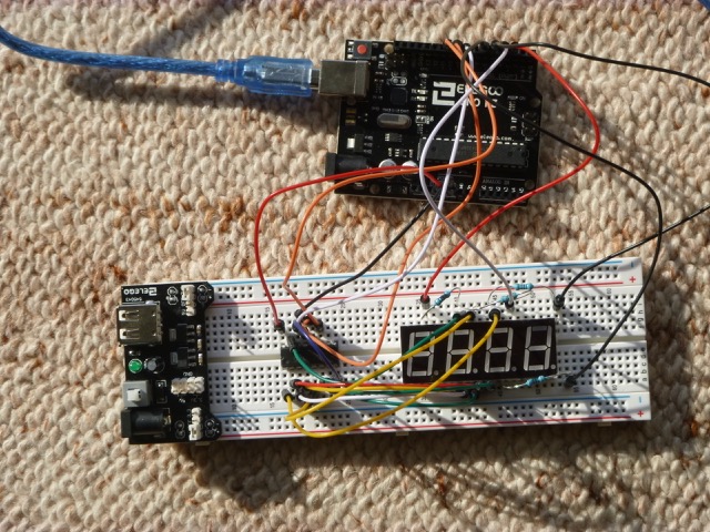
(4) Using a 3-digit 7-segment LED (cost few £). This is
accurate but needs lots of wires to connect up (even if using a shift register
to transfer the 7-segments serially). image of spaghetti here.
(5) A 2 line by 16 character LCD display is also inexpensive(£2-3). Using I2C
serial interface, this only needs 4 wires. It is not clear to me how "marine air
tolerant" this display is. This can display both the gallons and litres available.
(6) Since I only need a number output (tank volume available), I
explored using speech to output this to a speaker. Using the "talkie" library
on an Arduino, one can have a "cultured voice" (actually Kenneth Kendall )
read out the value on one of the Arduino pins as an audio file. I used a
surplus landline telephone earpiece as a speaker - this should be more marine
tolerant. To protect the Arduino which can only source about 20 mA, I put a
100Ω resistor and a 0.5μF capacitor (to remove any DC component) in
series with the earpiece (which had a DC resistance of about 100Ω). This
method uses only two leads to carry the signal.
(7) Getting the hang of this now - I used a 128x64 OLED dot matrix
display with an I2C serial driver (so 4 leads)(costing £2-3). This can
be arranged to give a nice accurate graphical display (to 1%) of the tank level - as well as
accurate numbers.
(8) Another option would be to generate NMEA2000 output
(effectively CANBUS) from the board - this is tricky (most probably needs a
board such as Arduino Due with more memory, etc, as well as a suitable
transceiver chip). Display would be the MFD (chart plotter). Work in
progress.
(9) As I wanted to display other information (
exhaust temperature - since my Vetus sender died), I decided to use a display
screen: Nextion NX4024T032_011. This model is 400 x 240 pixels, colour
and touch-screen., and has its own computing power inbuilt. It can be
driven from an Arduino by a serial line (2 wires - just sending numbers
to display) once the display is set up using a dedicated Nextion editor
(then loaded using a SD card). My implementation is here:
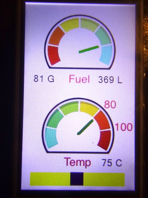
The slider at the
bottom allows the screen to be dimmed - essential on a boat at night.